
Inverse Kinematics for 3-DOF and 6-DOF Motion Control
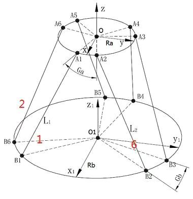

A platform pose is described by translation along X, Y and Z and rotation about those axes. For a Stewart platform, inverse kinematics calculates the six actuator lengths required to produce a requested pose.
Calculation Outline
- Define the six upper and lower joint coordinates in their local frames.
- Build the rotation matrix and translation vector for the requested pose.
- Transform each upper joint into the base coordinate frame.
- Calculate the distance from each transformed upper joint to its corresponding lower joint.
- Check actuator stroke, velocity, acceleration, joint angle and workspace limits.
Inverse kinematics is used for real-time command generation. Forward kinematics estimates pose from measured actuator lengths and normally requires iterative numerical calculation. Both algorithms depend on accurate geometry, coordinate conventions and calibration.